C64 Emulator in LabVIEW: The System Now Boots
A new release of my C64 emulator written entirely in LabVIEW brings an important achievement: the system now performs a full boot, loading the original Kernal and BASIC ROMs and displaying the classic Commodore 64 blue screen.
This post details the implementation of the core C64 subsystems: memory banking, video output, keyboard input, interrupt management, and audio synthesis explaining the technical choices made, the challenges encountered, and the optimizations applied to achieve a functional system in LabVIEW. While the emulator successfully executes BASIC programs and system code, significant work remains to achieve full hardware fidelity: the VIC-II lacks bitmap graphics and sprite support, the CIA implementation is partial, and advanced features like raster interrupts are not yet implemented. This document serves as both a progress report and a technical roadmap toward a complete C64 emulation.
Core System Architecture
The new bin\C64 main T.vi orchestrates the complete emulated system. This component integrates all implemented subsystems and manages the machine's lifecycle from boot to instruction execution. The main handles memory initialization, ROM loading, monitor startup, and the primary emulation loop.
Memory Banking and PLA
The C64's memory architecture relied on the PLA (Programmable Logic Array) chip to manage 64K of RAM alongside Kernal ROM (8K), BASIC ROM (8K), and Character ROM (4K)—exceeding the 64K addressing space through bank switching.
The PLA acted as a programmable memory controller, determining which memory region was visible to the CPU based on configuration register bits at address $01. This mechanism allowed dynamic mapping and unmapping of memory regions within the same address space. The Kernal and BASIC ROMs could be disabled to access underlying RAM, essential for exploiting the full 64K.
Below the C64 memory map as seen by CPU, source: C64 Wiki
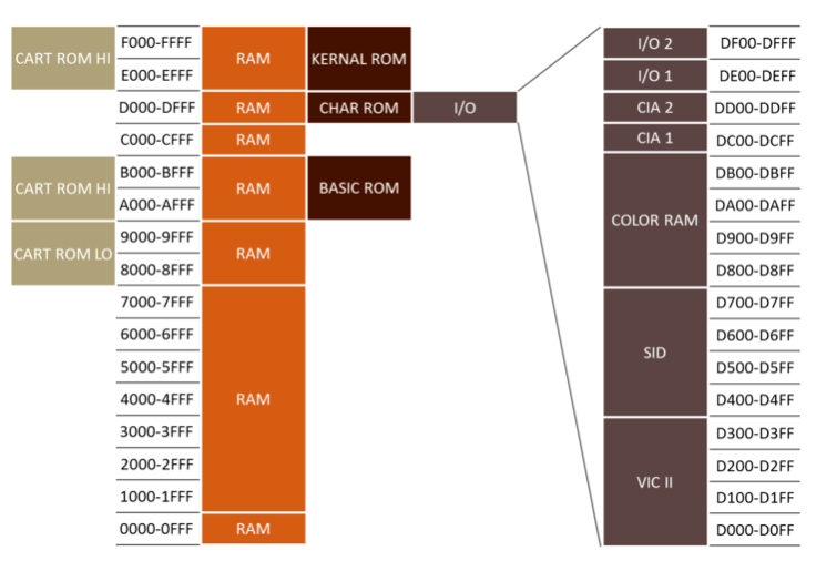
The emulator implements this banking logic through internal memory mapping tables. When the CPU executes read or write operations, the system checks the configuration register state and routes the operation to the appropriate ROM or RAM. Performance was optimized using LabVIEW's Data Value References (DVRs), enabling concurrent memory access without unnecessary data copying, significantly improving read and write speeds.
VIC-II, the Monitor (Preliminary)
The VIC-II video chip handled sprite hardware, scrolling, multiple graphics modes, and interrupt generation. This release implements a preliminary version supporting only standard text mode (40×25 characters).
The monitor, implemented in bin\screen\SCE screen main.vi, reads the C64's video memory (starting at $0400) and color map ($D800) to render characters on screen. The update mechanism differs from the original hardware: rather than per-scanline raster updates, the implementation updates per-character to accelerate rendering. Updates occur every 40ms, refreshing only characters or colors that changed from the previous frame, a significant optimization for LabVIEW's execution model.
Advanced VIC-II features remain unimplemented: bitmap graphics modes, sprites, hardware scrolling, and raster IRQ generation. These represent the next development targets.
CIA and Keyboard Management
The C64 used two CIA 6526 (Complex Interface Adapter) chips for peripherals and I/O. CIA1 primarily handled keyboard and joystick input, while CIA2 managed serial communication and user port interface.
The C64 keyboard was organized as an 8×8 matrix: 8 rows and 8 columns whose intersections defined 64 possible positions. When a key was pressed, it electrically closed the connection between a specific row and column. CIA1 cyclically scanned rows by writing to register $DC00 and read columns from $DC01 to determine which keys were pressed.
The emulator maps the PC keyboard to the C64's 8×8 matrix, emulating this scanning mechanism. The default mapping uses the Italian layout but is easily customizable through a text configuration file in bin\screen\SCE screen main.vi. When a PC key is pressed, the emulator updates CIA1 registers as if the corresponding C64 key were pressed.
The current CIA implementation is partial: it supports keyboard matrix management and Timer A (used for interrupt generation) but lacks the serial port, Time-of-Day clock, and NMI (Non Maskable Interrupt) functionality. The initial focus was on core functionality required for basic system interaction.
IRQ Management
The IRQ (Interrupt ReQuest) implementation represents a fundamental pillar of accurate emulation. Interrupts are signals allowing hardware to interrupt normal program execution flow to handle asynchronous events.
In the 6502/6510, when an interrupt is received and the I (Interrupt disable) flag in the status register is clear, the CPU completes the current instruction then:
- 1. Pushes the Program Counter (PC) and status register (SR) onto the stack
- 2. Sets the I flag to disable further interrupts
- 3. Loads the interrupt handler address from the IRQ vector ($FFFE-$FFFF)
- 4. Begins execution from the new location
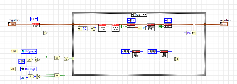
The Interrupt Service Routine (ISR) executes necessary operations to handle the event, then terminates with the RTI (Return from Interrupt) instruction, which restores the Program Counter and status register, allowing the main program to resume exactly where interrupted.
In the C64, interrupts were fundamental for numerous system operations:
- Keyboard scanning occurred via periodic interrupts
- VIC-II generated raster interrupts for synchronized graphics effects
- CIA timers provided precise timing mechanisms
The emulator implements complete IRQ logic in the 6502/6510 CPU, correctly handling the register save/restore sequence and jump to the interrupt vector. Currently, the only implemented interrupt source is CIA1 Timer A, configurable by software to generate interrupts at regular intervals.
The C64 Kernal exploited this mechanism to implement its "jiffy clock"—a counter incrementing every 1/60 second (NTSC) or 1/50 second (PAL)—used for system time management and keyboard scanning. Without proper IRQ handling, the system cannot detect keyboard input and many Kernal routines would fail.
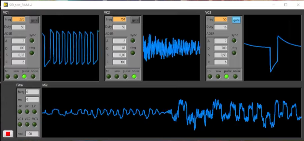
SID Improvements
The SID (Sound Interface Device) received significant enhancements in this release:
- Corrected audio filter: The SID featured programmable low-pass, high-pass, and band-pass filters with variable resonance. The implementation was refined for greater accuracy versus original hardware behavior
- DC Blocker: Added filtering to remove DC component from the audio signal, preventing unwanted clicks and pops
- Corrected ADSR: The ADSR (Attack, Decay, Sustain, Release) envelope generator was revised to more faithfully follow the original chip's temporal curves
- Memory-mapped integration: The SID is now correctly connected to the C64 memory map (registers $D400-$D41C), allowing programs to control it exactly as on real hardware
The new SID release executes every 0.25ms (versus 1ms in the previous version), making it musically more faithful when playing pieces that exploit frequent SID register value changes.
A demonstration of the new SID audio quality is available here:
These modifications significantly improve the emulator's audio quality, enabling music and sound demos with greater fidelity to the original.
Other details about the SID implementation are in a previous post
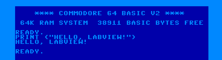
System Boot
The system now boots autonomously, loading the original C64 ROMs and presenting the classic startup screen:
This result integrates all components: memory banking making ROMs visible, the CPU executing Kernal code, the VIC displaying characters, the CIA handling keyboard, and IRQs maintaining system responsiveness.
The C64 boot sequence follows an elegant process:
- 1. At reset, the CPU reads the reset vector ($FFFC-$FFFD) from Kernal ROM
- 2. Kernal initializes all system chips (VIC, SID, CIA)
- 3. Memory test executes and available bytes are counted
- 4. Welcome message prints
- 5. BASIC interpreter starts
- 6. System enters a loop awaiting user commands
Future Development
Next steps for the emulator include:
Complete VIC-II Implementation
- - Bitmap graphics modes (320×200 multicolor and hires)
- - Hardware sprite system with collision detection
- - Raster interrupt generation for advanced graphics effects
- - Hardware scrolling and extended graphics modes
CIA Completion
- - Full implementation of Timer A and B with all operational modes
- - Time-of-Day clock for system time management
- - NMI interrupt handling
- - (Serial port for drives and cassette interface will not be implemented)
Program Loading
Since I will not implement external hardware support like disk drives and datassette, programs will be loaded directly into memory by the emulator. This simplified approach will still enable running games, demos, and applications while bypassing original I/O mechanisms.
Technical Notes
The project continues development in LabVIEW 2018, an unconventional language for this application type, but proving surprisingly adequate. DVR usage for shared memory management was fundamental for achieving acceptable performance, and LabVIEW's modular architecture facilitates incremental subsystem development.
Complete code is available on GitHub - C64 LabVIEW Emu, released under MIT license.